SANIL Electric (062404.KP)
The Awakening of U.S. Power Demand After the Three Decades of Stagnation
U.S. electricity consumption was essentially flat from the mid-2000 through 2020. The cause was not economic stagnation but a near perfect offset: efficiency gains from LED lightening, appliance standards, building insulation, and the offshoring of energy-intensive manufacturing absorbed the demand growth that population and GDP would otherwise have produced. American utilities operated for two decades on the assumption that load growth had ended. Transmission construction nearly halted, new generation was concentrated in gas combined-cycle plants and renewables, and the gird hardware industries including transformer manufacturing, contracted capacity accordingly.
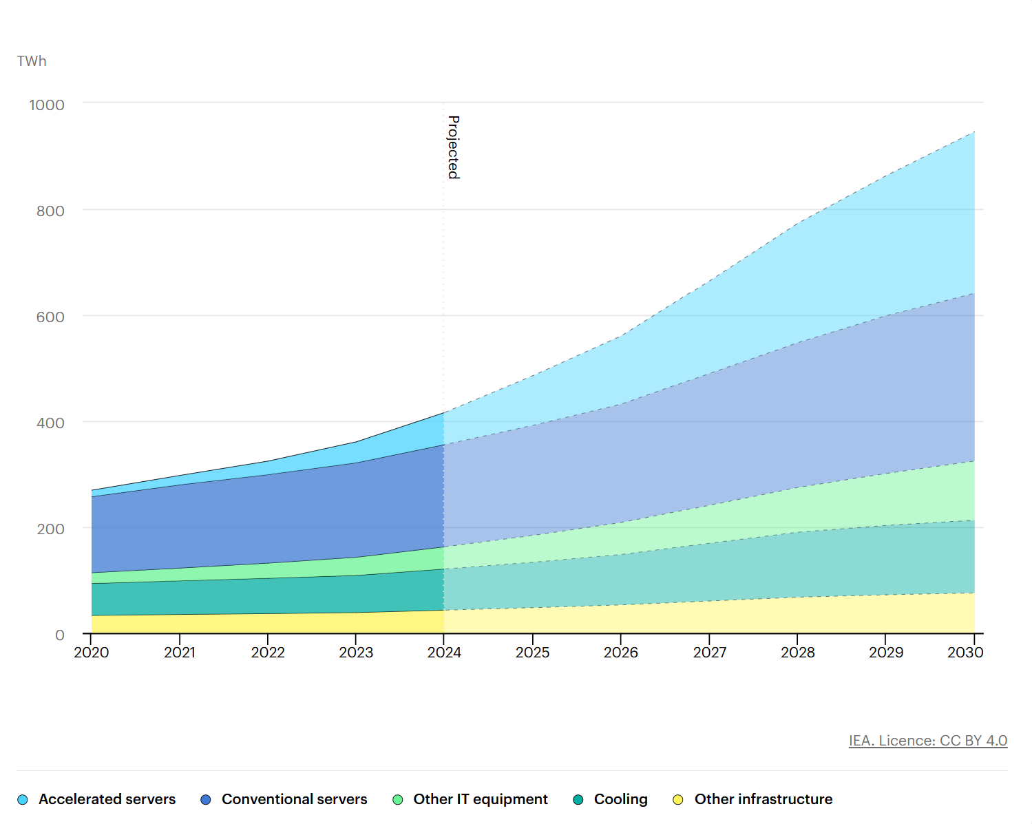
This equilibrium broke in 2022-2023. The IEA's Energy and AI report documents that consumption from data centers was approximately 415 TWh globally in 2024, about 1.5% of global electricity, having grown at 12% per year over the prior five years. Under the IEA Base Case, this consumption is projected to reach approximately 945 TWh by 2030, with growth of roughly 15% per year between 2024 and 2030, more than four times faster than overall electricity demand growth.
The geographic concentration is what makes this disruptive at the gird level. The United States accounted for 45% of global data center electricity consumption in 2024, China 25%, and Europe 15%. The IEA projects U.S. data center consumption to grow by approximately 240 TWh, a 130% increase, between 2024 and 2030. By the end of the decade, data centers will account for nearly half of all U.S. electricity demand growth, and the United States is on track to consume more electricity for data centers than for the production of aluminum, steel, cement, chemicals, and all other energy-intensive goods combined.
Drivers
Three forces drive the surge. AI training and inference is dominant: the IEA estimates that electricity consumption in accelerated servers, the category powering AI workloads, is growing at approximately 30% annually in the Base Case. Reshoring of semiconductor, EV battery, and advanced manufacturing capacity is the second driver, adding industrial load that did not exist on the U.S. soil five years ago. Electrification of transport and heating is the third, more relevant in the late 2020s and into the 2030s than in the immediate term.
At the hardware level, AI data centers represent an order of magnitude shift in load density. Single AI campuses now routinely require 100 MW or more, and announced megacampus target 1 GW, equivalent at one nuclear reactor's output. This reflects both the proliferation of high-power-density GPUs (Nvidia H100 at approximately 700W, B200 at approximately 1,200W per device) and the scaling of single site GPU counts past 100,000 units.
Region | 2024 Share of Global | 2024 to 2030 Growth |
|---|---|---|
United States | 45% | + 240 TWh (+130%) |
China | 25% | + 175 TWh (+170%) |
Europe | 15% | + 45 TWh (+70%) |
Asia except China | 3% | + 15 TWh (+80%) |
Global Total | 100% (415 TWh) | + 945 TWh by 2030 |
The Real Bottleneck: Transmission and Interconnection
The defining subtlety of the U.S. power crisis is that the binding constraint is not generation. The United States can build gas plant in 24 to 36 months and solar or wind farms on similar timeline when capital is committed. The choke point sits in the queue to physically connect new generation or new loads to the existing gird.
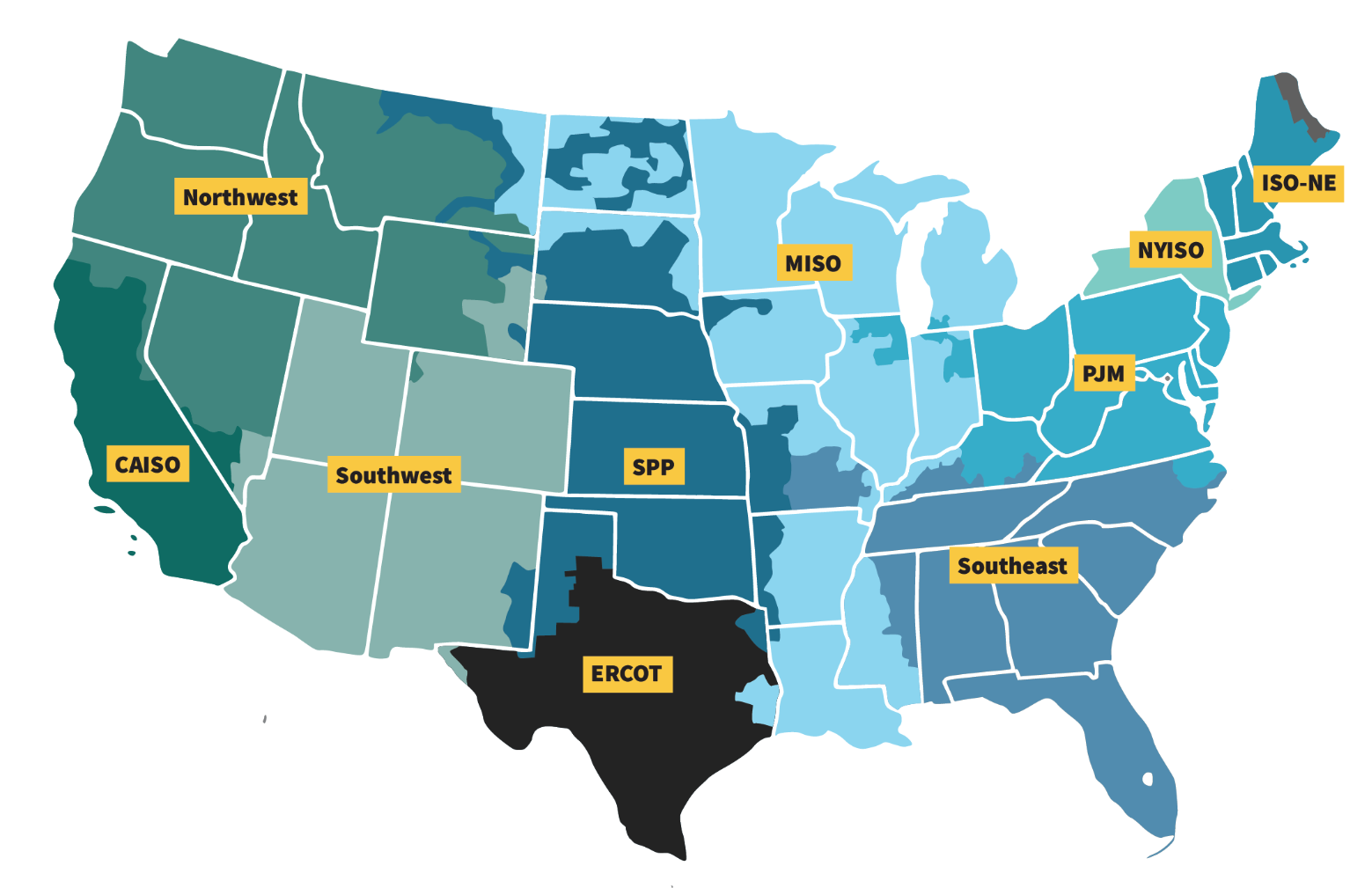
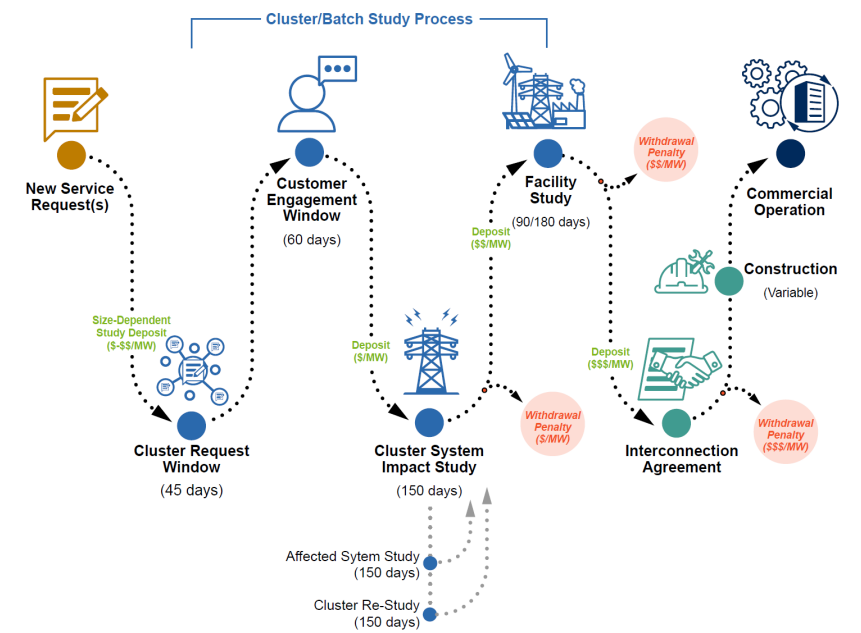
Every new power plant, every large industrial load, and every new data center must apply to its regional grid operator, one of seven ISOs and RTOs(PJM, MISO, CAISO, ERCOT, SPP, NYISO, ISO-NE) or one of dozens of non-ISO utilities, for an interconnection agreement. The operator runs a system impact study to determine what transmission upgrades the new entrant will trigger, calculates cost allocation, executes the agreement, and oversees construction of any required upgrades. The full process averages five years.
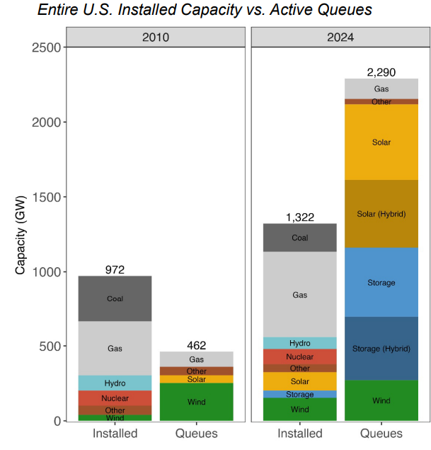
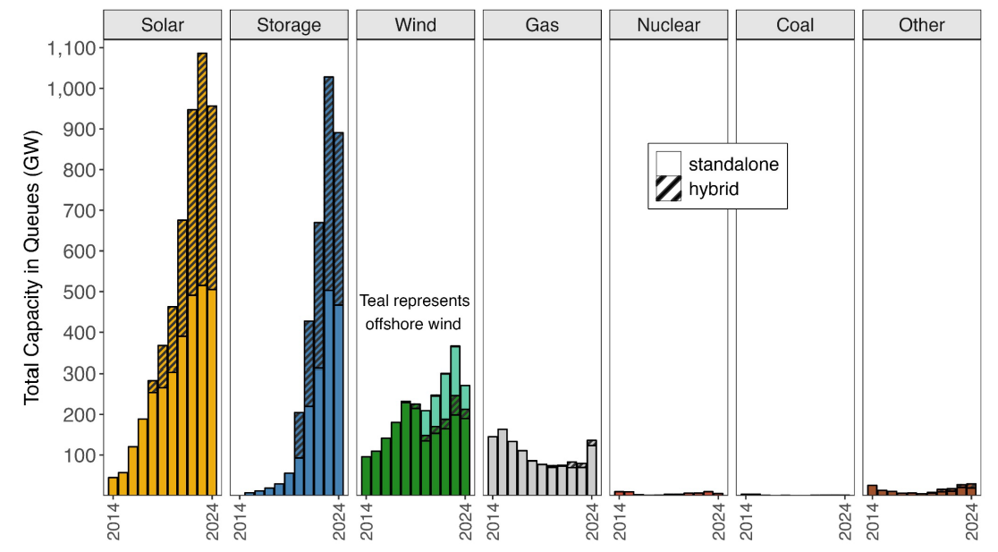
Lawrence Berkeley National Laboratory's Queued Up: 2025 Edition reports that as of year-end 2024, approximately 2,300 GW of total generation and storage capacity was actively seeking grid connection across roughly 10,300 projects: 1,400 GW of generation plus approximately 890 GW or storage. Total installed U.S. generating capacity is approximately 1,300 GW, so the active queue is roughly 1.7 times the country's entire fleet.
Three Findings That Sharpen the Picture
First, capacity that has cleared the regulatory hurdles still faces years of physical construction. Berkeley Lab reports that 408 GW of capacity already had a draft of executed interconnection agreement buy has not yet reached commercial operation.
Second, wait times are lengthening. The median duration from interconnection request to commercial operation has more than doubled from under two years for projects completed in 2000 to 2007 to over four years for projects completed in 2018 to 2024.
Third, and most significant for capital allocation, most projects in the queue never come out the other side. Only 13% of capacity that submitted interconnection requests between 2000 and 2019 had reached commercial operation by year-end 2024. 77% of that capacity had been withdrawn. The queue is best understood not as a backlog awaiting clearance but as a filter through which most projects fails.
Why the Queue Cannot Clear: Two Reinforcing Causes
The persistence of the queue is not a single problem with a single fix. It is the product of two distinct failures operating in parallel. The first is regulatory and procedural: gird operators cannot process applications fast enough, and even when they do, the cost-allocation and permitting frameworks are politically contested in ways that block resolution. The second is physical: even when an interconnection agreement is signed, the equipment required to actually build out the transmission upgrades (large power transformers, high-voltage cables, switchgear) is itself in sever global shortage, with lead times that often exceed the contracted construction schedule.
Either cause alone would create meaningful delay. Together, they create a structural blockade that cannot be relieved within the AI investment cycle. The next two sections examine each cause in turn, beginning with the regulatory and procedural side as illustrated by the most extreme U.S. case, and then turning to the equipment side as the more global and harder-to-solve constraint.
The 2024 Composition Shift
One development in the most recent data deserve particular attention. Active natural gas capacity in the queue rose to 136 GW at year-end 2024, up 72% year-over-year, while solar (956 GW, down 12%), storage (890 GW, down 13%), and wind (271 GW, down 26%) all declined. This single statistic captures the underlying policy and market turn. Gas is sudden back in the queue at scale because data center developers and utilities increasingly believe it is the fastest dispatchable capacaity that can actually be built and connected. The IEA forecasts that natural gas generation will expand by 175 TWh globally to meet data center demand through 2035, the largest dispatchable contribution after renewable.
The IEA places a forward-looking number on the constraint: unless these grid risks are addressed, approximately 20% of planned data center projects globally are at risk of delay.
The Regulatory and Procedural Cause: The Texas Case
Texas is the cleanest illustration of how the regulatory and procedural side of the queue breaks down under sustained demand pressure. ERCOT, the TEXAS gird operator, is functionally isolated from the rest of the United States, a deliberate political choice that historically allowed Texas to operate its own deregulated power market without federal oversight. The structural cost is that when ERCOT runs out of headroom, Texas cannot borrow capacity from neighboring grids.
Texas became the natural destination for AI data center development through a combination of inexpensive land, the lowest commercial electricity rates in the country, business-friendly state policy, and abundance Permian Basin natural gas. Hyperscalers and colocation operators concentrated development around Austin, Dallas, and Houston, and ERCOT's interconnection queue exploded as a result.
ERCOT's own December 2025 Report on Existing and Potential Electric System Constraints and Needs documents the scale of that the scale of that explosion directly. As of December 17, 2025, the volume of large load interconnection requests in ERCOT's queue had reached 238.6 GW, up from 63 GW at year-end 2024, a nearly fourfold increase in a single year. Approximately 77% of that demand came from data centers seeking to connect by 2030. Cumulatively, only 7,502 MW of large loads had been approved to energize since January 2022, less than 1% of the pending queue. ERCOT's 2031 demand forecast in the same report was revised to 218 GW, up from 150 GW just one year earlier, with the increase explicitly attributed to officer-attested data center load growth.
The supply side could not absorb this. ERCOT reported that between 2024 and 2025, the grid actually added approximately 23 GW of new generation capacity, with another 9 GW slated for early 2026. Against 238.6 GW of pending load requests, the gap was structural rather than cyclical.
Texas Senate Bill 6 (SB 6), signed by Governor Abbott on June 20, 2025, was the legislative response. The law applies to larges loads of 75 MW or greater at a single site and establishes a $100,000 minimum interconnection fee, uniform site control and financial commitment requirements, mandatory disclosure of duplicate interconnection requests filed elsewhere in Texas, and grid infrastructure cost-allocation rules applicable to large-load customers. Most consequentially, SB 6 directs the Public Utility Commission of Texas (PUCT) to establish a mandatory demand management program requiring protocols to curtail large loads of 75 MW or more interconnected after December 31, 2025 during firm load shed events, with limited exceptions for critical loads. ERCOT's own implementation rules under SB 6 were approved in May 2025 and took effect on December 15, 2025. The PUCT has until December 2026 to complete the broader rulemaking.
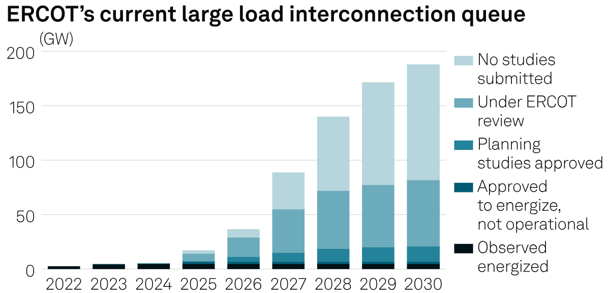
The implication is that even data center operators willing to pay above-market rates for Texas connection face a structural constraint with two layers. The gird operator itself has publicly stated it cannot process application fast enough, and the system has acquired legal authority to curtail their consumption during grid emergencies. A data center developer's ability to operate its facility in Texas at expected utilization is now contingent on ERCOT's discretion under SB 6's curtailment protocols.
Why the Texas Pattern Generalize
Texas is the most extreme U.S. case, but the underlying dynamic is universal. Every regional grid operator in the country faces the same combination: a fixed pool of impact-study engineers, a years-long backlog of applications, and a political-economy problem in which any system upgrade requires deciding who pays. PJM paused new application reviews entirely in 2022. MISO delayed its 2023 application window into 2024. CAISO's Cluster 15 was pushed from 2022 to 2023.
The regulatory cause of the queue is therefore solvable in principle. through additional staffing, FERC Order 2023 reforms, or cluster-study process improvements, but each of these reforms has multi-year implementation timelines, and none addresses the second cause. Even if every grid operator doubled its application processing capacity tomorrow, the queue would still face a hard physical ceiling: there is not enough transmission equipment in the world to build out the upgrades the cleared applications would require.
That second cause is what determines whether the queue can clear in time for AI cycle. It is not a regulatory problem and cannot be solved by regulatory reform. It is a manufacturing problem.
The Physical Cause: Why Transformers Became Unbuildable
The most critical piece of equipment in any transmission upgrade is the large power transformer. It also the piece of equipment whose global supply has tightened most severely in the past three years. Without an adequate supply of transformers, no amount of regulatory reform or queue-processing acceleration can produce actually built transmission capacity. This is the binding physical constraint behind the Berkely Lab finding that 408 GW of capacity has signed interconnection agreements but has not yet reached commercial operation
How a Power Transformer Works
A power transformer takes the voltage produced by a generator (typically 13.8 to 24kV) and steps it up to transmission voltage (345,500, or 765kV in the U.S. system). At substation near load centers, additional transformer step the voltage back down through stages, 345 to 138kV, 138 to 69kV, and finally to distribution voltage (13.8 to 34.5kV) and consumer voltage (480V industrial or 240V/120V residential). Every interface in the system requires a transformer. The U.S. grid contains approximately 60 million distribution transformers and tens of thousands of large power transformers in service.
When a new data center signs an interconnection agreement that requires upgrading the substation feeding its site, what physically has to happen is that one or more new power transformers must be manufactured, shipped, installed, tested, and energized. This is the gating step. If the transformers is not available, the interconnection agreement is just paper.
Why a 765kV Transformer Is Hard to Build
Construction of a large power transformer requires a tightly constrained set of inputs. The core is built from Grain-Oriented Electrical Steel (GOES), a specialty product whose magnetic grain structure is precisely aligned to minimize energy loss. Globally, fewer than ten companies produce utility-grade GOES at scale, including POSCO, Nippon Steel, JFE, Cleveland-Cliffs, ThyssenKrupp, Stalprodukt, and Baoshan. Finally assembly takes six to nine months of skilled labor, and the global pool of qualified transformer engineers is aging out faster than it is being replaced. Final factory testing requires high-voltage test facilities that exist at perhaps a dozen sites worldwide.
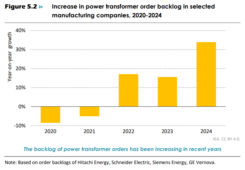
The IEA reports that power transformer order backlogs at the four largest global manufacturers (Hitachi Energy, Schneider Electric, Siemens Energy, and GE Vernova) grew by more than 30% in 2024, following two consecutive years of growth above 15%. The cumulative effect is a backlog roughly 60 to 80% larger than at the start of the AI cycle in 2022.
Power transformer prices, according to the IEA's index, has risen by 1.5x since 2020. The report further notes that in some segments, units with high complexity or specialized design, prices have reached 2.6x pre-pandemic levels in real terms. Grain-oriented electrical prices doubled between 2021 and 2023 and remain approximately 60% above 2020 levels. Because GOES production is concentrated in fewer than ten producers globally and because new GOES production capacity takes years to commission, this cost driver is structural rather than cyclical.
The Korean Position in Global Transformer Trade
According to IEA, global trade in power transformers grew 80% between 2018 and 2023. Within that growth, China, Italy, Korea, and Turkiye collectively account for half of all global trade, with China alone contributing a quarter. On the import side, both the United States and Europe have more than doubled their transformer import value since 2018.
The IEA names Korea explicitly as one of the top-three sources of U.S. power transformer imports, alongside Mexico and Europe. Korean share of U.S. medium- and large- transformer imports rose from 5.2% in 2020 to 16.8% in 2024, a roughly threefold increase. In distribution transformers (small units below 500 kVA), Korean share rose from 1.1% to 18.6%, a seventeenfold increase, while Chinese share collapsed from 15.8% to 6.7% as tariff and security concerns took hold.
But Data Center Operators Cannot Wait
- Model Cycle
AI model generations turn over on an 18 to 24 month cadence. GPT-4 launched in March 2023, GPT-5 followed in August 2025, and the underlying GPU generation behind them (H100 in 2022, H200 in 2024, B200 in 2024 to 25, and the announced next generation) have followed a similar rhythm. A data center that comes online five years late misses two complete model generations of competitive positioning. For hyperscalers spending $50 to $100 billion or more in annual AI infrastructure capex per their 2025 disclosure, being two cycles behind is not a delay. It is strategic exit.
- The Revenue Scale
Industry consultant estimates indicate that a 400 MW AI data center generates approximately $10 to $12 billion in annual revenue at typical hyperscale colocation pricing. What is undisputed is that a single GW-scale AI campus generates billions in annual revenue, and even six months of delay represents revenue measured in billions of dollars. Against this opportunity cost, paying a premium for accelerated gird connection, or for an alternative power architecture entirely, is straightforward economics.
- The Political Layer
In March 2025, the Trump administration negotiated commitments from major hyperscalers (Amazon, Google, Meta, Microsoft, Oracle, OpenAI, and xAI) under what was reported as a "ratepayer protection" framework, requiring large new data center loads to bring their own generation rather than burdening existing utility ratepayers. The direction reality is well-established: U.S. residential electricity rates rose roughly 6% in 2025, much of it attributed to data center load growth, and political pressure on hyperscalers to internalize their power infrastructure has become bipartisan.
The Forced Conclusion: On-Site Generation as the Only Available Answer
The combination of the three pressure (the model cycle, the revenue scale, and the political framework) leads developers to a single conclusion. If grid connection cannot be obtained on the required timeline, and if waiting is not a viable option, then power must come from somewhere other than the gird. The data center must generate its own electricity on its own site, behind its own meter, on its own schedule. This is the on-site generation pivot, and it is no longer a hedge or a backup strategy. For new AI campuses entering development in 2025 and beyond, it is the primary architecture.
The question that immediately follows is which technology can actually deliver on-site generation at the scale and speed AI data centers require. That question has only one credible answer at present, and the next section walks through the elimination logic that produces it.
The Technology Filter: Why Bloom Energy Emerged as the Reference Solution
Once an AI data center developer commits to on-suite primary generation, the field of viable technologies narrows quickly. The decision criteria are stringent: the system must be deployable in months rather than years, must scale to hundreds of megawatts at a single site, must operate continuously at high utilization for years, must comply with the air quality and permitting regimes of the jurisdictions where data centers are built, and must be commercially available now rather than promised for the future. Each of these criteria eliminates candidates.
The Four Candidates and Their Constraints
Gas turbines are the most familiar option, and in principle that natural fit. They are dispatchable, scale to hundreds of megawatts, and have decades of utility deployment history. The problem is supply. The IEA report documents that approximately two-thirds of global gas -fired power plants turbines come from three suppliers (GE Vernova, Siemens Energy, mitsubishi Power), and that lead times for new turbine deliveries have stretched to multiple years and in some cases approach seven years for specific models. Some hyperscaler developers are paying premiums to move forward in the queue, but the fundamental constraint is factory capacity, not pricing. In addition, large gas turbines trigger air quality ppermitting that can take years in jurisdictions like California and Virginia where many data centers are sited. A turbine that arrives in 2030 does not solve a 2026 problem.
Diesel reciprocating engines are widely used as data center backup but were never designed as primary generation. Running them continuously for years would create unacceptable air quality and noise impacts in the populated areas where data centers operate, and would not pass environmental permitting in most U.S. jurisdictions for primary use. Diesel works as a generator for occasional outages, not as a way to keep a data center running 24/7.
Small modular reactor are the long-term answer many policymakers and developers prefer. Microsoft, Amazon, and Google all signed agreements with SMR developers (Oklo, X-energy, Kairos Power, NuScale) for future deployments. The IEA report notes that the first MSRs are expected online around 203, with broader commercialization through the 2030s. For a data center that needs power in 2026 or 2027, SMRs are not a deployable option. They are part of the decade-out solution, not the decade-in solution.
Solid oxide fuel cells (SOFCs) are the remaining candidate. SOFCs convert natural gas, biogas, or hydrogen directly into electricity through an electro-chemical reaction without combustion. Because there is no flame and no rotating machinery, the system produce essentially no NOx, SOx, or particulate emissions, which makes air quality permitting straightforward in jurisdictions where gas turbines would face years of review. Because they are modular (typical commercial units in the hundreds of kilowatts to low megawatts, scaling to hundreds of megawatts through aggregation), they can be manufactured in factories on standardized production lines and shipped to sites for rapid installation. The deployment timeline from order to operation is measured in months rather than years.
Why SOFC Specifically Fits the AI Data Center profile
Beyond deployability, SOFCs have three operational characteristics that match the AI data center use case. First, they are designed for continuous high-utilization operation; unlike gas peaker or diesel backup generators, they perform best when running near their rated output, which is exactly the AI workload profile. Second, because the output is initially DC, SOFC systems are architecturally aligned with emerging high-voltage DC distribution standards inside data centers (the 800VDC architecture that hyperscalers are increasingly adopting), reducing conversion losses. Third, SOFCs are fuel-flexible: they can run on natural gas today and transition to hydrogen as that supply chain develops, without replacing the underlying generation hardware. This protects the developer against future regulatory shifts on natural gas combustion.
The Commercial Reality
These technical advantages would be theoretical if no one had built SOFCs at the scale data center require. The relevant question for an AI hyperscaler is not whetehr a technology could in principle be deployed at 100 MW or 1 GW, but whether someone has actually done it and whtether the supply chain can deliver more. On this question, the field of commercial SOFC supplies is extraordinarily narrow. Bloom Energy is the only company in the world with installed SFOC capacity in the hundreds of megawatts, with an active manufacturing footprint capable of scaling to gigawatt-class deployments, with multi-decade operational history in commercial environments, and with a customer book that already includes hyperscalers and major utilities. Other SOFC developers exist (Ceres Power in the UK, mitsubishi Power's MEGAMIE platform in Japan, several startups in various stages) but none match Bloom on installed scale, manufacturing readiness, or commercial track record.
This narrowing is the reason a single name keeps appearing whenever data center operators, utilities, and policy bodies discuss on-site primary generation for AI infrastructure. The bottleneck logic forces developers toward on-site generation; the deployment timeline forces them toward SOFC; the commercial scale requirement forces them toward Bloom Energy. The IEA's analytical framework arrived at the same conclusion through independent investigation, which is what makes its citation in Energy and AI significant.
The IEA's Direct Citation of the AEP-Bloom Energy Agreement
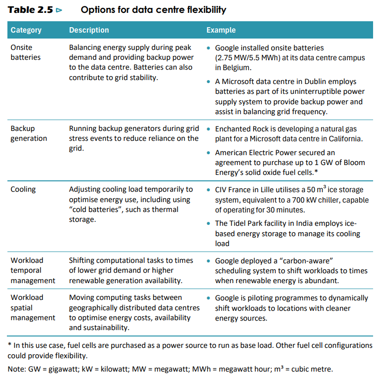
In Table 2.5 of Chapter 2, the IEA presents what it identifies as the principal options for data center flexibility. The table contains five categories: on-site batteries, backup generation, cooling load adjustment, workload temporal management, and workload spatial management, Under each category, the IEA cites specific reference deployment by named companies.
Under the backup generation category, the IEA cites two examples. The first is Enchanted Rock developing a natural gas plant for a Microsoft data center in California. The second is, in the IEA's exact framing, that American Electric Power secured an agreement to purchase up to 1 GW of Bloom Energy's solid oxide fuel cells. This is the only fuel cell technology and the only fuel cell company referenced by name anywhere in the IEA report.
The IEA appends a critical footnote to its citation of the Bloom Energy reference: "In this use case, fuel cells are purchased as a power source to run as base load. Other fuel cell configurations could provide flexibility." This footnote reframes the entire citation. The IEA is acknowledging that Bloom is being deployed not as occasional emergency backup but as continuous primary power. The 1 GW figure therefore represents continuous generation capacity, not standby capacity sized for outage coverage. This is a fundamentally different, and far larger, market category.
What This IEA citation Establishes
The placement of the AEP-Bloom agreement in the IEA's authoritative analytical framework establishes three propositions that would be difficult to assert credibly without independent verification.
First, that Bloom Energy is the reference platform for solid-oxide fuel cell deployment at gigawatt scale globally. The IEA examined the global landscape and chose Bloom as its named example. Second, that base-load on-site fuel cell deployment is now a recognized category of data center power architecture, not an experimental or marginal use case. The IEA does not include speculative technologies in its primary tables. Third, that AEP, the fifth larges U.S. utility, has placed its institutional credibility behind the architecture by committing procure up to 1 GW. This procurement is by definition a multi-year program; 1 GW of fuel cell capacity cannot be deployed in a single contract year.
Why Bloom Specifically, Not SOFCs In General
The fact that SOFCs as a technology class meet the three requirements is not the same as the fact that any SOFC supplier can deliver them. The relevant question for an AI hyperscaler placing a multi-year, hundred-megawatt-scale order is not whether a technology could in principle work, but whether someone has actually deployed it at the required scale and whetehr the supply chain can scale further. On this question, the field of commercial SOFC suppliers is extraordinarily narrow.
Bloom Energy has installed cumulative SOFC capacity in the hundreds of megawatts across approximately 1,100 sites in nine countries. The company manufactures cells in Fremont, California, and assembles systems in Newark, Delaware, with a domestic manufacturing footprint specifically protected from import tariff risk. The company holds 380 active U.S. patents and 252 international patents. Operational availability across its installed base since 2020 is approximately 99.9%. other SOFC developers exist (Ceres Power in the UK licenses technology to multiple original equipment manufacturers, Mitsubishi Power's MEGAMIE platform operates in Japan, several startups are in various stages of commercialization), but none match Bloom on installed scale, manufacturing readiness, commercial track record, or the specific combination of operational availability data and customer references that a hyperscaler procurement organization requires.
This narrowing produces a structural consequence. When AEP committed to up to 1 GW of fuel cells, the technical and commercial diligence that preceded that commitment identified Bloom as the only supplier capable of executing at that scale on the required timeline. When Brookfield established the $5 billion AI Infrastructure Fund with explicit reference to fuel cell projects, the same diligence reached the same conclusion. When the IEA selected one fuel cell company to cite by name in its principal flexibility options table, the company they selected was Bloom. These are not coincidences. They are the same finding arrived at independently by three different institutional analyses, each of which examined the global landscape and concluded that the bottleneck-breaking technology is currently embodies in one commercial supplier.
The Strategic Implication for Supply Chain Positioning
The implication for investment purposes is precise. If the bottleneck-breaking technology is SOFC, and if the commercial deployment of SOFC at AI data center scale is concentrated in Bloom Energy through the AEP, Brookfield, and SK ecoplant channels, then the entire downstream supply chain that Bloom assembles to execute against those channels becomes investable as a function of Bloom's volume trajectory. The supply chain that Bloom assembles is not generic; it is the specific set of vendors that Bloom has qualified to deliver the investors, transformers, control systems, structural components, and balance-of-plant equipment required for SFOC microgird deployment at hundreds of megawatts of scale.
This is where the analysis shifts from technology to commerce. The question is no longer whether Bloom will deploy gigawatts of capacity over the next decade; the IEA citation, the AEP commitment, the Brookfield financing facility, and the OBBBA tax credit restoration together make that outcome the base case rather than the speculative case. The question is which suppliers inside Bloom's qualification process will capture the largest share of the gigawatt-scale buildout, and on what terms. That question has a specific answer in the transformer category, and the answer is Sanil Electric.
Sanil Electric's Position in Bloom Energy's Suuply Chain
The transformer category inside a Bloom microgrid deployment is not a commodity procurement. The interface transformer that sits between Bloom's inverter output and the data center distribution system bears the full harmonic burden, the full voltage regulation responsibility, and the full grid-forming requirement during islanded operation. The engineering requirements on that single transformer are far more stringent than for any single transformer in a conventional grid-connected configuration. The question is who can actually engineer and manufacture transformers that meet those requirements at the scale and on the timeline Bloom's deployment program demands.
The Architectural Match: Why an SOFC Interface Transformer is Engineered Like a Renewable Inverter Transformer
To understand why Sanil's existing engineering capability translates so precisely to Bloom's requirements, the starting point is the physics of how a solid oxide fuel actually produces electricity, and what that physics demands from the transformer that sits between the fuel cell array and the data center load. The connection is not analogical or marketing-driven. It is electrical engineering at the level of waveform, harmonic spectrum, and control loop design.
How an SOFC Produces Power and Why That Creates a Specific Electrical Challenge
A solid oxide fuel cell is fundamentally a DC device. Inside each cell, oxygen ions migrate across a ceramic electrolyte at approximately 700 to 900 degrees Celsius, and the resulting electrochemical reaction produces direct current at low voltage, typically under one volt per cell. Bloom's commercial product stacks thousands of these cells in series and parallel to produce useful voltage and current levels, but the output remains DC. To deliver t hat power to an AC grid or an AC data center load, every Bloom system must include a power conditioning system (PCS) that converts DC to AC using high-frequency switching power electronics, typically Insulated Gate Bipolar Transistors (IGBTs) operating at switching frequencies of several kilohertz.
The AC output of that PCS is not a clean 60 Hz sine wave. It is an 60 Hz fundamental waveform with significant harmonic content at multiple of 60 Hz (the 5th harmonic at 300 Hz, the 7th at 420 Hz, the 11th at 660 Hz, the 13th at 780 Hz, and so on), plus high-frequency switching ripple in the kilohertz range. The harmonic spectrum and amplitude depend on the specific PCS topology, modulation scheme, and filter design, but every inverter-based power source produces this characteristic non-sinusoidal output. The transformer that receives this output cannot be designed for clean 60 Hz operation; it must be engineered specifically to tolerate continuous operation in a harmonic-rich environment without overheating, saturating, or accelerating insulation degradation.
This is the fundamental electrical engineering reason why Bloom cannot use a standard utility distribution transformer for this grid interface. A standard utility distribution transformer is optimized for clean sinusoidal current at 60 Hz, the environment that exists downstream of large synchronous generators. Subjecting that transformer to the harmonic-rich output of an inverter array for years of continuous operation would produce three failure modes. The first is winding overheating because eddy-current losses scale with the square of frequency; the harmonics at 5x, 7x, 11x, 13x of fundamental frequency dissipate disproportionately more heat in the cooper windings than the fundamental does. The second is core overheating from increased hysteresis losses at higher frequencies. The third is accelerated insulation aging from the elevated voltage stresses that harmonic distortion creates across winding insulation. A utility-grade transformer placed in this environment would reach end-of-life in a fraction of its design life, and would likely fail catastrophically before then.
Why Solar and Wind Inverter Transformers Solve Exactly the Same Problem
A solar farm or a wind farm produces electricity through fundamentally different physics from an SOFC, but the electrical engineering problem at the point of grid interconnection is identical. A solar panel produces DC. A wind turbine produces variable-frequency AC that is rectified to DC and then re-inverted to grid-frequency AC. In both cases, the output that reaches the interconnection transformer is the AC product of high-frequency power electronic switching, with same harmonic spectrum, the same switching ripple, and the same continuous duty cycle as Bloom's PCS output. The transformer at the interconnection point must do the same three things in either case: tolerate continuous harmonic-rich current without overheating, regulate voltage in coordination with the inverter's reactive power control loop, and support grid-forming operation if the system needs to island.
This is why Sanil's twenty-six-year engineering relationship with TMEIC, fifteen-year relationship with GE Renewable Energy, and ongoing engagement with Siemens produces exactly the engineering capability that Bloom requires. TMEIC is one of the world's largest manufacturers of solar and wind inverters, GE Renewable Energy operates one of the largest renewable inverter portfolios globally, and Siemens supplies inverters across utility-scale renewable projects worldwide. The transformers Sanil has been designing, prototyping, testing, and shipping to these three customers for the past two and a half decades have been engineered to a specification that, when described in physics terms rather than application terms, is essentially identical to what Bloom's SOFC application requires.
The Specific Engineering Characteristics Bloom Needs and Sanil Has Already Built
Three specific design characteristics distinguish a microgrid-grade interface transformer from a standard utility transformer. Each maps directly onto an engineering capability that Sanil has developed through its renewable-inverter work.
The first is harmonic-tolerant core and winding design. To withstand the elevated eddy-current losses that harmonics produce in copper windings, the windings are typically constructed from Litz wire (multiple thin insulated strands twisted together rather than a single solid conductor), which mitigates the skin effect that concentrates high-frequency current at the conductor surface. To withstand elevated hysetersis losses in the core, the steel laminations are typically thinner than in a utility transformer (often 0.23 mm or thinner versus the 0.30 mm or 0.35 mm common in utility designs), reducing eddy currents within each lamination at the cost of additional manufacturing complexity. To handle the elevated voltage stress that harmonic distortion creates across winding insulation, the insulation system uses higher dielectric strength materials and additional insulation margins. Sanil has been engineering exactly these characteristics into its solar and wind inverter transformers for decades.
The second is voltage regulation and reactive power capability coordinated with the PCS. A transformer that simply transforms voltage levels is insufficient for microgird applications. The inverter and the transformer must operate as a coordinated voltage regulation system, where the inverter adjusts its reactive power output in milliseconds to maintain voltage at the AC bus within tight tolerance, and the transformer is engineered to handle the resulting reactive currents without core saturation. This requires designing the transformer with adequate magnetic margin to absorb reactive power swings, specifying the leakage reactance precisely so that the inverter's control algorithms can predict the transformer's response, and coordinating the per-unit impedance with the PCS designer's expectations., Sanil's product engineering teams have done this coordination repeatedly with TMEIC, GE, AND Siemens PCS engineering teams over their long relationships.
The third is grid-forming capability for islanded operation. This is the most subtle and most architecturally important distinction. A grid-following transformer, the kind used in most utility distribution applications, relies on the larger grid to set frequency and voltage; the transformer is passive and simply transforms what the grid provides. A grid-forming transformer system, by contrast, can establish and maintain a stable 60 Hz frequency reference on its own when the grid is disconnected, in coordination with a grid-forming inverter that uses internal control algorithms to synthesize a stable AC waveform from the DC input. This capability is what allows a Bloom microgrid to keep the data center running when the surrounding utility grid is down, in maintenance, or curtailed. It requires the transformer to be designed for operation across a wider range of voltage and frequency conditions than a grid-following transformer, to handle the transient currents that occur during transitions between grid-connected and islanded modes (synchronization events that can produce inrush currents several times the nominal rating), and to operate without the stabilizing influence of a large synchronous generator on the grid side. Sanil has built grid-forming transformers for solar-plus-storage microgrid applications since at least the late 2010s, when the renewable industry began deploying these systems for commercial and industrial customers. The same engineering capability transfers directly to Bloom's SOFC microgrid configurations.
Why Conventional Utility Transformer Manufacturers Cannot Easily Enter This Market?
To understand why the incumbent transformer manufacturers are not natural competitors for Bloom's specification, despite being vastly larger and better-capitalized than Sanil, it helps to look at what those manufacturers actually optimize for in their core business. The Category divergence is not a marketing distinction. It is reflected in the design rules engineers use, the steel grades they buy, the test equipment they own, the certifications they pursue, the field engineering experience they accumulate, and the customer relationships they cultivate. Each of these differences compounds over years and decades into two distinct engineering disciplines that share the word "transformers" but otherwise have surprisingly little in common.
Where Sanil Has Spent Three Decades Building Different Capabilities
The core distinction is that Sanil and the large incumbent manufacturers (Hyundai Electric, Hyosung Heavy Industires, Hitachi Energy formerly knows as ABB, Simens Energy's utility division, Schneider Electric, GE Vernova's utility division) are solving two different physics problems that happen to share the word "transformer."
The incumbents optimize for the transmission grid: extreme high voltage (345 to 765 kV), surviving lightning surges and fault currents, and the lowest cost per MVA. Their power source is the synchronous generator, which produces a clean sine wave, so harmonic tolerance is barely a design consideration for them. They are genuinely world-class, but a different problem.
Sanil spent three decades optimizing for the opposite environment: the inverter. Solar inverters, wind inverters and no SOFC power conditioning systems all produce harmonic-rich, non-sinusoidal output that would overheat and destroy a standard utility transformer. Sanil's customers from the start were the inverter makes themselves, so harmonic tolerance, voltage coordination with the inverter, and gird-forming capability for island operation were the design center, not edge cases.
This difference is builty into five concrete things that took decades to accumulate and cannot be bought quickly. The steel is different (thinner, lower-loss laminations versus standard utility grade). The windings are different (Ltiz wire to defeat the skin effect versus solid cooper). The insulation is different (more thermal margin to survive harmonic heating). The certifications are different (CESI, KEMA, KERI harmonic and environmental type tests versus utility test protocols). And the field experience is different (deserts, polar regions, offshore marine versus controlled substations).
The result for the Bloom thesis is this: an SOFC produces DC, which a power conditioning system convert to harmonic-rich AC, which is electrically identical to the environment Sanil has engineered for since the late 1990s. Bloom cannot use utility-grade transformer because it would cook itself in that environment within a few years. The incumbents could in principle enter, but acquiring the institutional engineering knowledge, certifying new designs, and clearing Bloom's vendor qualification takes years, which exceeds the window of the AEP deployment program through 2030.